In almost all manufacturing environments, even in semiconductor fabs, information is exchanged between the logical participants according to the principle of the automation pyramid in accordance with ISA 95. This standard divides store floor systems into different levels. At the bottom is the sensor/field level. The PLC/machine level builds on this. The subsequent SCADA/control system level (Supervisory Control and Data Acquisition) is developed differently in different industries. MES (Manufacturing Execution System) and ERP (Enterprise Resource Planning) form the upper part of the pyramid. The ISA 95 principle states that one level initially only communicates directly with the level below or above it. A simple example: the SCADA system gives a command to a machine, e.g. to start a production process, but does not act directly on a sensor on this machine. This communication principle has proven its worth to date, as it is clear and allows responsibility for certain systems to be separated.
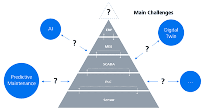
Figure 1: Automation pyramid and new information technologies
Level |
Question (selection) |
Data |
| ERP | For which customer was the screw manufactured? | Order data |
| MES | When was the screw manufactured?
In which batch was the screw manufactured |
Batch data |
| SCADA | Which raw material batch was used? How was the machine loaded | Shop floor logistics data |
| PLC | Which NC program was used?
Were there any malfunctions during turning/milling? Which tool was used |
Machine data |
| Sensor | What was the performance data of the machine’s axis drives? | Sensor/actuator data |
The problem is that only very little data is reported upwards along the information flow of the automation pyramid. Typically, data is aggregated or simply not processed further. In our example, we can consider whether the actual performance axis data for processing the specific screws is actually stored in the ERP system. In most cases, this is not the case.
In order to obtain data from all systems in all layers of the automation pyramid, a third dimension of communication is required, as well as a data platform in which all relevant data can be stored homogeneously. New information technologies such as the digital twin can dock onto the data platform and thus have access to all data in the automation pyramid.
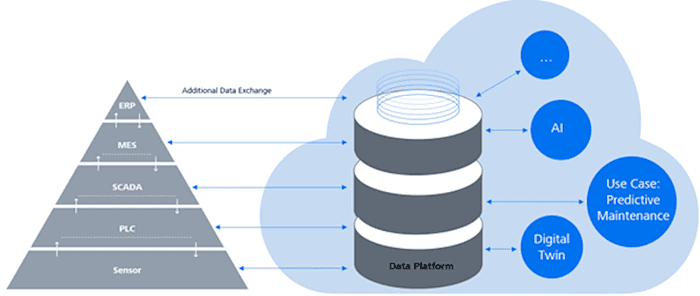
Figure 2: Additional data exchange with a data platform
But what do these new communication channels look like?
At ERP and MES level, access is comparatively simple. Most applications offer interfaces (Application Programming Interface, API) that can be easily used with the help of appropriate documentation. As the characteristics of the SCADA level vary greatly from industry to industry, there is no general solution. A solution must be found for each specific application. At PLC level, the OPC UA (Unified Architecture) standard for communication with machines appears to be gaining acceptance. At sensor/field level, there is a wide variety of provider-specific solutions, meaning that there are currently no standards. In some fieldbus systems, it is possible to transfer sensor data directly to third-party systems via the fieldbus coupler. In some cases, sensor manufacturers are already implementing another data channel in addition to the standard interface, such as WiFi in combination with the MQTT protocol.
Machine data as the largest data source on the store floor
Modern machines are generally already highly automated these days. The entire sensor system of the machine is measured cyclically, digitized signals are processed by the PLC and put into context in order to subsequently output the corresponding control commands to the actuators. In addition to the often proprietary data transfer to the human-machine interface, where operators can usually transfer commands to the machine via a touch panel, OPC UA has become the quasi-standard as an open and standardized interface in many important industries such as the automotive and pharmaceutical industries. The simplest use case, namely the provision of user data via OPC UA Direct Access, is implemented as standard. There is a so-called OPC UA server on the machine, which continuously publishes user data. A higher-level system can load data from the machine via OPC UA Client and process it accordingly. The actual or actual data of the machine is transferred. As the data available on the OPC UA server can be explored live using the browsing function, the type and content are often only described in the machine-specific documentation. This is often sufficient for this use case.
If, on the other hand, the machine is also to be controlled by the higher-level system, a more complicated communication scenario is required, as the server and client have to interact with each other. The implementation of a state machine is recommended. This consists of a state variable and OPC UA methods that can be used to trigger the transition from one state to another. The OPC UA client triggers the method of a transition. Parameters can even be added to the method at this point. The machine checks whether the state transition is actually possible and sets the state variable again if it is successful. Ideally, an additional event is triggered asynchronously by the OPC UA server, which in turn informs the OPC UA client that the new state has actually been reached. Figure 3 shows a highly simplified state model of a machine with only two states. Common use cases such as machine status control, recipe transfer, communication with upstream and downstream machines in the process or controlled tool changes require much more complex communication scenarios. Extensive documentation on the information model must be created here. If you are aiming for industry-wide, cross-company standardization, it makes sense to publish the information model in so-called OPC UA Companion Specifications, which are then also managed by the OPC Foundation.
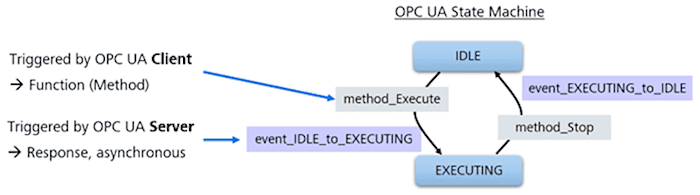
Figure 3: OPC UA State Machine
Any written standardization can be misinterpreted
Every communication interface must be documented, whether in project-specific documents or generally accessible Companion Specifications. In most cases, the documentation takes the form of PDF documents. The problem with any description in natural language (which is usually enriched with tables and diagrams) is that it still has to be interpreted. This inevitably leads to ambiguities and errors. Furthermore, a realized implementation of an interface cannot be tested completely without the corresponding partner being available with its part of the interface. In order to solve this omnipresent problem in the context of OPC UA communication, software was developed with which a behavior simulation of the interface can be created. The behavior of the OPC UA client and the OPC UA server can be modeled graphically for a communication scenario based on an information model. The PETRI network principle was chosen as the description language, as this is already highly formalized and easy to understand. This allows not only the so-called “happy flow” in communication to be represented, but also various error scenarios. The result is a behavioral model for both communication partners. These behavioral models can now be automatically compiled into stand-alone simulation programs, which are then available as simple applications.
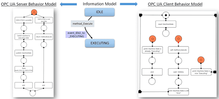
Figure 4: Behavior models in the form of PETRI networks (simplified representation)
These simulation applications can now be easily exchanged between the communication partners. The owner of the OPC UA server (corresponds to the machine supplier) receives the simulation model of the OPC UA client – and vice versa. This means that each partner is now able to develop a part of the interface and test it in detail. With this procedure, actual plug & play can now take place during commissioning of the interface. Valuable commissioning time on the store floor is saved and development resources can be used effectively.
Conclusion
OPC UA is ideal for making machine data accessible to a higher-level data platform. Furthermore, bidirectional communication is easy to implement with state machines. Both advantages are the basis and enabler for modern digital services such as artificial intelligence and digital twins. In order to significantly accelerate the implementation of the interface and improve its quality, software was developed that can be used to graphically create an additional behavioral model of the two communication participants around an existing information model. These behavioral models can be converted into independent simulator applications and can then be exchanged between the communication partners. This gives each partner the chance to test their own interface 100%.
_ _ _ _ _ _
Author:

Marco Grafe
Solution Specialist for Smart Manufacturing and Digital Transformation | ZEISS Digital Innovation
Marco Grafe works as “Solution Specialist for Smart Manufacturing and Digital Transformation” at ZEISS Digital Innovation and bundles the development activities around Industry 4.0. He uses practical experience from 15 years as an engineer in mechanical and plant engineering, especially in the semiconductor, automotive and pharmaceutical industries.
_ _ _ _ _ _
This article was published exclusively for NEXT “In Focus: Software”.